
VERSALIFT TMD-2047-T Insulated derrick with Turret mounted winch including the following items:
• Boom assembly consists of the lower boom, intermediate boom, upper boom, and extension system. The lower boom is constructed of high strength steel forming a 9.75 x 12.75 rectangular section. The intermediate boom is constructed of high strength steel forming an 8 x 10.13 rectangular section. The upper boom is constructed of high strength, fi lament wound, epoxy resin, fiberglass with a 7 x 9 rectangular section and incorporates a fiberglass tip. The extension system includes two double-acting hydraulic cylinders. Each cylinder incorporates dual counterbalance holding valves.
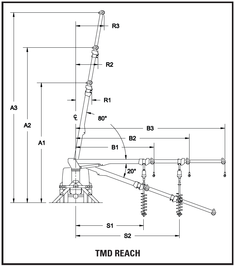
• Boom lift cylinders are dual double-acting cylinders equipped with dual counterbalance holding valves and self-aligning spherical bearing. Each cylinder is capable of fully supporting the rated lifting capacity of the derrick.
• Turntable is constructed from 5/8” plate wings and a 1.5” thick base plate. The base plate is machined flat to support the rotation bearing.
• Rotation drive consists of a hydraulically driven worm and spur gear acting on a shear ball rotation bearing. The gearbox incorporates a load sense feature to measure the side loads applied to the boom.
• 15,000 lb. maximum capacity turntable winch consists of a worm gearbox, hydraulic motor, holding valve, and drum. At 40 GPM flow, the winch provides an average line speed of 35 fpm.
• Hydraulic overload protection is purely hydraulic and uses no electronics or electrical components. The system senses the boom lift cylinder pressure and side loads at the rotation gearbox. When an overload condition is detected, the system disables the following: digger dig, winch raise, boom lower, upper boom extend, and intermediate boom extend.
• Transferable pole guide can be pinned to either the inner boom tip or the intermediate boom. The pole guide includes hydraulic tilt and hydraulic operation of the pole claws. Holding valves are included to lock both cylinders in position.
• Pole guide interlock prevents inner boom from extending unless either of the following conditions is satisfied: 1. The pole guide tilt is fully raised. 2.Or the pole guide is properly pinned to the upper boom.
• Continuous rotation is continuous and unrestricted in either direction.
• Pins, bearings and lubrication – The main pivot and cylinder joints use high strength hard chrome plated steel pins with fiberglass reinforced Teflon non-lube bearings.
• Open center hydraulic system uses a tandem gear pump system which supplies a combined 40 GPM for the digger and winch circuits and 15 GPM for the boom functions.
• 50-gallon bulkhead mount reservoir includes cleanout, 10 micron return filter that can be replaced without draining the reservoir, dipstick, 100 mesh (149 micron) suction screen, gate valve, and magnetic drain plug.
• Fiberglass insulation is certified for 46kV and below in accordance with ANSI A10.31 dielectric rating requirements.
• 52 in. tall pedestal is a fabricated steel structure incorporating a 1.5” thick top plate which is machined flat to support the rotation bearing.
• Sub-frame is full length and constructed of 6 x 6 square tubing and 5/16” plate.
• Main outriggers are designed and constructed from high-strength steel. At maximum extension the outriggers provide 158” of spread and 7.9” of penetration based on a 40” frame height. Outriggers are equipped with pilot operated check valves, internal thermal relief valves, and separate operating controls for each outrigger. Slide pads at each leg ensure smooth operation. The standard pivot feet swivel a minimum of 10° each way.
• Auxiliary A-frame outriggers are designed and constructed from high-strength steel. At maximum extension the outriggers provide 151” of spread and 6.1” of penetration based on a 40” frame height. Outriggers are equipped with pilot operated check valves, internal thermal relief valves, and separate operating controls for each outrigger. Slide pads at each leg ensure smooth operation. The standard pivot feet swivel a minimum of 10 each way.
• Outrigger boom interlock system is designed to prevent the boom from operating until the outriggers contact the ground. It also prevents the outriggers from being retracted before the boom is properly stowed.
• Outrigger motion alarm will sound while the outriggers are in motion.
• Riding seat lower controls with T handle consists of a turntable mounted deck, seat, access ladder, and control console. Includes full pressure, full flow hydraulic controls with a single handle joystick for boom raise-lower, rotate, and intermediate boom extend-retract. Additional hydraulic valve levers are included to control winch, dig, upper boom extend, pole guide tilt, and pole claw open-close.
• Digger assembly consists of the digger hanger (which is automatically transferred from the lower boom to the intermediate boom when the auger is unstowed) and the auger stow bracket includes an over-stow protection valve.
• Winch line is 1” diameter x 100 ft. Stable Braid
• 7 ton rated swivel hook
• Digger drive is two speed 12,000/3,000 ft-lb. with 2-1/2 in. hex
• 72 in. Kelly Bar (auger extension) for 2-1/2 hex drive to 2-1/2 auger
• Auger – 18 in. auger with Rock Ripper Head
• Auger stow sling with 7/8” diameter synthetic rope.
• Digger/winch pressure gauge on the lower control panel senses the pressure generated while using the digger and winch.
• Boom load indicator gauge on the lower control panel senses the pressure generated in lower boom cylinders as a percentage of maximum.
• Custom load capacity chart.
• Engine start/stop control operated by a toggle switch at the lower controls.
• Throttle control is variable speed foot operated pedal used to control the engine speed from the lower control station.
• Tool/Pole puller tool circuit consists of a hydraulic sectional valve with integrated adjustable flow control and pressure relief. The 3-position control valve allows operation of a tamper or pole puller, while still allowing operation of the digger at the same time
• Complete unit is primed and painted prior to assembly. The standard color is white urethane.
• Slope indicators shall be installed to indicate the level of rotation bearing relative to the ground.
• Two (2) Operator’s Manuals, two (2) Service Manuals, one (1) Manual of Responsibilities, and one (1) EMI Safety Manual are included with each aerial lift.
Line Body to the following specifications:
• 156 in. x 54 in. x 94 in. line body including the following:
• Stainless steel automotive rotary type door latches and hinges.
• Chain stops on all compartment doors.
• Rubber rolled crown type fenders and automotive bulb type weather stripping.
• Master door lock system.
• Two (2) under body mounted 20” x 20” x 4” outrigger pad holders
Street side compartments:
• 1st vertical: Five (5) fixed material hooks.
• 2nd vertical: Two (2) adjustable shelves with dividers
• 3rd vertical: Two (2) adjustable shelves with dividers
• Horizontal: Adjustable dividers on compartment bottom
• Rear vertical: Five (5) fixed material hooks.
• Hot stick: 156 in. long with wood lined shelf and rear dropdown access door.
Curbside compartments:
• 1st vertical: Five (5) fixed material hooks.
• 2nd vertical: Tread plate access steps to bed area with grab handle on each side
• 3rd vertical: Two (2) adjustable shelves with dividers
• Horizontal: One (1) removable divider shelf with dividers
• Rear vertical: Five (5) fixed material hooks.
• Tail shelf: 30 in. tread plate tail shelf.
• Rear lighting: 9-lamp light bar installed at rear of tail shelf and rubber mounted recessed rear lighting kit with incandescent lights.
• Wheel chock storage: – One (1) each side built into wheel wells.
Cab and chassis to the following specifications:
• 2025 International HV507 4×4 cab and chassis.
• Full chassis specifications available upon request.
Installation to include the following:
• Install VERSALIFT TMD-2047-T, mounting hardware, PTO, and pump
• Install line body and no-skid treadplate floor black.
• Install back up alarm, park brake interlock and slope indicators
• Install quick disconnects with dust caps at the ground tool power
• Relocate glad hands to the rear of the body
• Install 3-point grounding system
• Install a ground reel with 50’ of 1/0 black cable and a hydraulic hose reel with 50’ of conductive hose
• Install two (2) amber strobe lights off of the lower boom rest
• Install a BP100A 15-ton pintle hitch, two (2) safety “D” rings, 6 prong and 7 prong trailer receptacles
• Install ICC rear bumper
• Install start/stop switch at the rear of the body
• Install a single pole rack with ratchet tie down straps
• Install mud flaps, electronic brake controller
• Furnish fire extinguisher and a 3-piece triangle reflector kit
• Furnish four (4) wooden outrigger pads and two (2) rubber wheel chocks
• Test ride completed unit for 1 hour
• Test and Certify per ANSI A92.2