
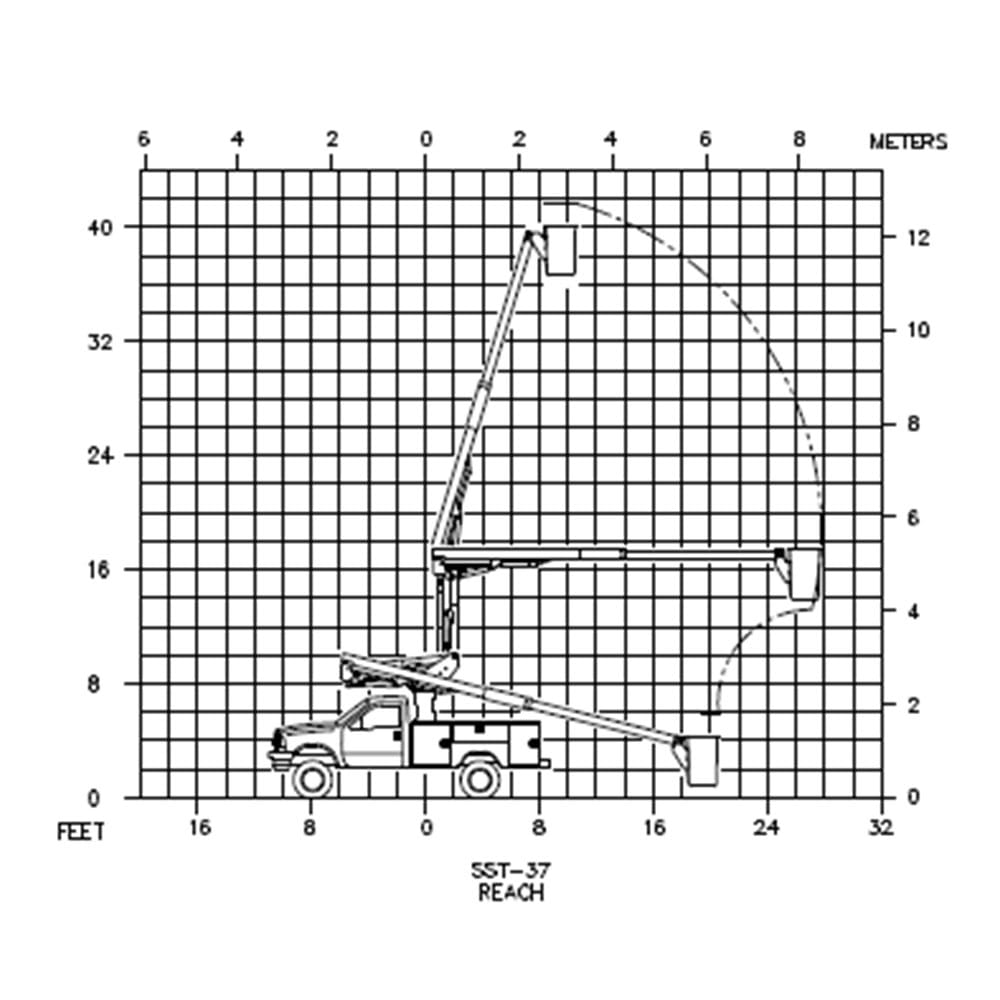
VERSALIFT SST-37-ENH; non-insulated end mounted 37 ft. (11.3 m) telescopic aerial platform lift, 42 ft. (12.8 m) working height, 27 ft. 9 in. (8.5 m) horizontal reach including the following items (based on a 40 inch frame height):
AERIAL LIFT SPECIFICATIONS
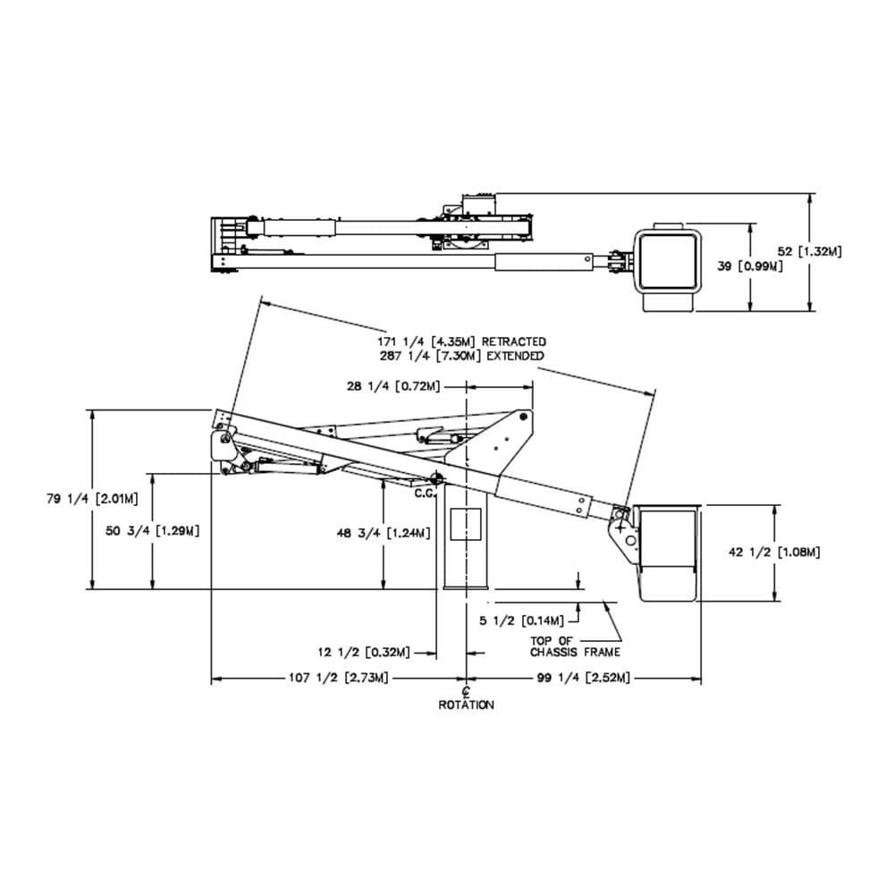
PLATFORM – The fiberglass platform is 24 in. x 30 in. x 42 in. (0.61 m x 0.76 m x 1.07 m) deep with an inside and outside step for easy access. The platform capacity is 300 lbs. (136 kg). A tubular rubber support for the platform is provided.
PLATFORM COVER – A vinyl cover is supplied for the platform.
PERSONNEL RESTRAINT SYSTEM – A safety harness and lanyard are supplied. The anchor for the lanyard is attached to the upper platform support.
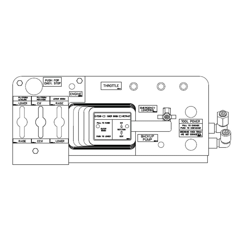
SINGLE STICK 3-AXIS PLATFORM CONTROL – The Unitrol single-stick 3-axis control consists of a multi-jointed handle which operates the control valve. A safety trigger located on the underside of the single stickhandle will not allow boom movement until it is depressed. The control valve is full pressure and full flow. The operator can feather between the three control movements to provide multi-function boom action. An emergency stop control is provided.
ROTATING PLATFORM – Provides 180° hydraulic platform rotation.
HYDRAULIC PLATFORM LEVELING – Platform leveling is controlled by a master and slave cylinder arrangement. The platform leveling system can be activated from the upper controls to adjust platform leveling, tilt the platform for cleaning, or to ease the removal of an injured operator.
OUTER/INNER BOOM ASSEMBLY– The outer/inner boom assembly includes an outer boom, telescopic inner boom, extension system, and hose assemblies. The outer boom consists of a 6 in. x 8 in. (150 mm x 200 mm) steel section and a 7.5 in. x 9.5 in. (190 mm x 240 mm) fiberglass section (Electrogard) that maintains a 42 in. (1.08 m) insulation gap with the inner boom fully retracted. The 5 in. x 7 in. (130 mm x 180 mm) rectangular fiberglass inner boom is housed within the outer boom. The extension system consists of a hydraulic cylinder, two holding valves, and a hose carrier housed entirely within the boom assembly. The hoses routed through the outer/inner boom assembly are non-conductive and fully contained within the boom assembly. The outer/inner boom assembly articulates from 14° below horizontal to 74° above horizontal. Actuated by a double acting cylinder with a holding valve, the outer/inner boom assembly is offset to one side to provide easy access to the platform. A tie-down strap is included.
COMPENSATED LOWER BOOM – The lower boom consists of a 6 in. (150 mm) square steel section. The SST-37 lower boom articulates from 7° below horizontal to vertical for a total travel of 97°. A compensation link forms a parallelogram linkage to maintain the outer/inner boom assembly at a constant angle to the turret.
PINS – Pins are high-strength alloy steel which are chrome plated for a hard finish and corrosion resistance. Pins are bolted in place with a welded pin tab at one end and a pin cap at the other for redundant retention.
CYLINDERS – Both the outer and lower boom cylinders are a threaded end-cap design. The lower boom and extension cylinders are equipped with two holding valves to prevent down creep and to lock the booms in position in the event of hose failure. The outer boom cylinder is equipped with one holding valve.
TURRET – The turret wings are ½ in. (13 mm) thick steel plate. A steel tube is welded between the turret wings to support the boom cylinder and provide rigidity. The turret plate is machined flat to support the rotation bearing. A bearing cover is provided to prevent foreign material from interfering with lift rotation.
CONTINUOUS ROTATION – Rotation is continuous and unrestricted in either direction. An electric and hydraulic collector ring assembly provides a path for hydraulic oil and electric signals from the pedestal to turret. Rotation is accomplished by a hydraulically driven worm and spur gear set acting on a shear-ball rotation bearing. The critical bolts holding the turret to the rotation bearing and the bearing to the pedestal are grade 8 hex head cap screws. These critical bolts are marked with a torque seal indicator to provide a quick means to inspect for relative movement. A slotted adjustment is provided for pinion and rotation gear clearances. An external hex drive is provided for manual rotation in case of hydraulic failure.
PEDESTAL – The pedestal is a round shape with an access opening on both sides. The 12 gallon (45 l) hydraulic reservoir is built integral to the pedestal. A 100-mesh suction screen and 10-micron return line filter are located inside the pedestal. The top plate is 1 ¼ in. (32 mm) thick and machined flat to support the rotation bearing.
HYDRAULIC OIL RESERVOIR – Designed as an integral part of the pedestal, the reservoir has an anti-splash baffle and easy to read fluid level gages. The oil capacity of the reservoir is 12 gallons (45 l), which is sufficient for a 5 GPM (19 lpm) hydraulic tool circuit.
INDIVIDUAL LOWER CONTROLS – Individual full pressure controls at the turret actuate all boom functions. The lower control station is equipped with a selector valve to override the upper controls.
LUBRICATION – Non-lube bearings are used at all points of motion. The rotation bearing is the only component that requires periodic lubrication.
HYDRAULIC SYSTEM – The open-center hydraulic system operates at 3 gpm (11.4 lpm) at 2250 psi (158 kg/cm2). The pump draws oil through a 100-mesh suction screen. A 10-micron return line filter with bypass valve is included. Fluid level gages are furnished for checking fluid level.
HOSES AND FITTINGS – The hoses routed through the booms are high pressure and non-conductive with swaged hose end fittings. Nylon sleeves are installed over hoses at points of movement. Reusable fittings can be installed if a hose is damaged.
AUTOMATIC THROTTLE CONTROL – Automatically advances the engine idle speed when the PTO is engaged.
BACKUP PUMP – An auxiliary hydraulic pump designed to bring the booms down in case the main hydraulic source fails. This system consists of a hydraulic pump driven by a 12V DC motor, which is powered by the truck engine battery. The system is connected in parallel with the main pump and is designed for non-continuous operation. An air cylinder at the platform and a toggle switch at the pedestal energize this system. When used with continuous rotation, an additional pass in the collector assembly is usually required.
ENGINE START/STOP AND MASTER CONTROL – The start/stop circuit has been designed so that the lift cannot be operated unless the truck ignition key is in the “run” position and the master switch is “on.” This feature makes it difficult for unauthorized individuals to operate the lift when the truck is locked. An air cylinder at the platform and a toggle switch at the turret are provided to actuate the engine start/stop control.
PAINT – The complete unit is primed and painted prior to assembly. The color is Extreme Climate white urethane.
SLOPE INDICATORS – Slope indicators are required on Versalift units and supplied by Time Manufacturing Co. Slope indicators shall be installed to indicate the level of the rotation bearing relative to the ground.
LIFT EYE – Mounted below the platform mount, which allows lifting loads up to 350 lbs. (159 kg) with the platform empty and the inner boom retracted.
MANUALS – Two (2) Operator’s Manuals, two (2) Service Manuals, one (1) Manual of Responsibilities, and one (1) EMI Safety Manual are included with each aerial lift.
CHASSIS SPECIFICATIONS
- 2023 Ford F-550 4X4 XL Regular Cab Chassis
- 3L DEVCT NA PFI V8 engine
- 10-speed auto torqshift transmission
- 145” wheelbase; 60” cab to axle
- Heated power glass/manual fold mirrors
- Tow hooks
- Trailer brake controller
- Power locks and windows
- Steering tilt/telescope
- Cruise and audio controls on steering wheel
- Remote keyless entry
- SYNC w/ 8” screen
- 88 rear axle ratio
- Platform running boards
- 19,000 lbs. GVWR
- Engine block heater
- 50 state emissions
- Spare tire and wheel with jack
- 40 Gallon aft axle fuel tank
- 410 amp alternator
- Dual batteries
- Rear view camera and prep package
- Oxford White exterior
- Medium Dark Slate vinyl interior
BODY SPECIFICATIONS
Fiberglass Service Body:
BFXB 108
Body Dimensions:
- Overall Length: 108”
- Overall Width: 94”
- Pack Depth: 20”
- Pack Height: 42”
- Floor Width: 54”
- Mounting Height: 25”
Body Details:
- Steel Understructure – Alum Tread Floor
- Smooth Aluminum Bulkhead
- Aluminum Tail Skirt
- Standard Bright White Gelcoat
- Stainless Steel Rotary Latch
- Type 304 Stainless Steel Hardware
- Type 304 Stainless Steel Door Hinge
- Vinyl Covered S/S Cable Door Stops
- Gas Prop Door Retainer Kit
- Vertical Doors
- Non-Skid Compartment Tops
- Clear Vinyl Rock Guards
- Black Plastic Fuel Bezel (1 Standard)
- Automotive Grade Bubble Gasket
- One Piece Molded Doors With
- Automotive Finish Both Sides
- Recessed Door Jambs
- Flow Through Ventilation System
- Removeable Wheel Well Panels
- White Compartment Interiors
- Recessed Door Seal System
- Light Adaptor For Ford Chassis
- Full Led Lighting Package 1
- Stop / Tail / Turn / Marker & Back-Up Light
Streetside Compartmentation:
- 1st Vertical – Two (2) adjustable shelves with dividers.
- Horizontal – One (1) shelf with dividers.
- Rear Vertical – Seven (7) adjustable hooks, 2-3-2.
Curbside Compartmentation:
- 1st Vertical – Two (2) adjustable shelves with dividers.
- Horizontal – One (1) shelf with dividers.
- Rear Vertical – Seven (7) adjustable hooks, 2-3-2.
Additional Features:
- Flexglo compartment lighting top and sides of each compartment
- Aluminum tread tailshelf, 30”
- Drop down door each side with thru storage
- Two (2) Aluminum pool style tailshelf grab handles curbside of tailshelf.
- Cable stirrup step curbside of tailshelf.
- Automotive undercoat
- Push/Pull rod lock system
INSTALLATION DETAILS
- Furnish and install mounting hardware, PTO, and pump
- Install VERSALIFT SST-37-ENH
- Furnish and install hydraulic diagnostic test ports
- Furnish and install body and accessories
- Furnish and install park brake interlock
- Furnish and install slope indicators
- Furnish and install backup alarm
- Furnish and install ballast as needed
- Furnish and install a four (4) LED amber strobes. Mounted two on the grill and two at the tailshelf.
- Furnish and install an ICC bumper
- Furnish and install a pintle plate with D-ring each side
- Furnish and install a combination pintle hook with 2-5/16” ball
- Furnish and install a 7 prong trailer receptacle
- Furnish and install mud flaps
- Furnish and install travel height decal in the cab
- Furnish and install a set of rear overframe torsion bars
- Furnish and install a protective eyebrow above the chassis back up camera at the rear
- Furnish a 5lb fire extinguisher and a 3-piece triangle reflector kit
- Furnish two (2) rubber wheel chocks
- Test ride completed unit for 1 hour
- Test and Certify per ANSI A92.2