
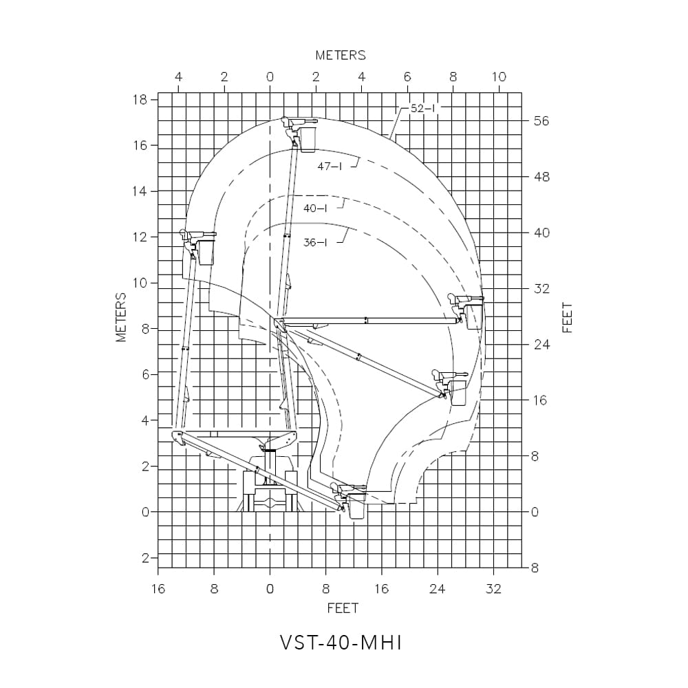
VERSALIFT VST-40-MHI, Insulated 40 ft. 4 in. (12.3 m) telescopic aerial platform lift, 45 ft. 4 in. (13.8 m) working height, 30 ft. 2 in. (9.2 m) horizontal reach including the following items (based on a 40 in. (1.02 m) frame height):
AERIAL LIFT SPECIFICATIONS
PLATFORM – The closed fiberglass platform is 24 In. x 30 In. x 42 In. deep (.61 m x .76 m x 1.07 m) with an inside and outside step for easy access. The platform capacity is 400 lbs. (181 kg) with the jib and winch installed and 500 lbs. (227 kg) with the jib and winch removed. The platform is equipped with a tubular rubber rest/support.
PLATFORM LINER AND VINYL COVER – A 50 kV rated liner and soft vinyl cover are supplied for the platform.
PERSONNEL RESTRAINT SYSTEM – An Arc flash rated safety harness and lanyard are supplied. The anchor for the lanyard is attached to the platform support.
INDIVIDUAL LOWER CONTROLS – Individual full pressure controls at the turret actuate all boom functions. The lower control station is equipped with a selector valve to override the upper controls.
SINGLE STICK 3-AXIS UPPER CONTROL – The full pressure single-stick 3-axis upper control includes a safety trigger to prevent inadvertent operation. The lift movements correspond with control handle movements. An emergency stop and a tool selector control are located at the upper controls.
TRUGUARD™ – This advance upper controls isolation system provides 4″ of electrical isolation from the entire upper controls, including the control dash panel. This system also includes a protective shield which helps prevent environmental and work related contaminants from making direct contact with the isolating surfaces.
HYDRAULIC PLATFORM ROTATION – A hydraulic rotary actuator, operated by a control lever, rotates the platform 180° from one side of the boom, to the end-hung position, and to the other side of the boom.
HYDRAULIC PLATFORM LEVELING – A master and slave cylinder controls platform leveling. The leveling system can be operated from the upper or lower controls to adjust platform leveling, tilt the platform for clean out, or to ease the removal of an injured operator.
HYDRAULIC TOOL CIRCUIT AT THE PLATFORM – This system is intended for open center hydraulic tools. The tool circuit provides 6 gpm (22.7 lpm). A pressure reducing valve in the tool circuit limits the tool pressure. The valve can be adjusted from 1000 to 2500 psi (70 to 175 kg/cm2).
LINE-LIFTING SOCKET – Built as part of the platform support structure, is a vertical line-lifting socket for 3 in. (76 mm) diameter line-lifting attachments. The socket is automatically leveled with the platform without any manual adjustments.
OUTER/INNER BOOM ASSEMBLY – The outer/inner boom assembly includes an outer boom, telescopic inner boom, extension system, and hose assemblies. The outer boom consists of an 8” x 10” (203mm x 254mm) steel section, with a 9” x 11” (229mm x 279mm) fiberglass Electroguard section. The 6 ⅞” x 8 ⅞” (165mm x 216mm) rectangular fiberglass inner boom is housed within the outer boom. The extension system consists of an extension cylinder, holding valves, and a hose carrier housed inside the boom. The hoses routed through the outer/inner boom assembly are non-conductive and fully contained within the boom assembly. A double acting cylinder with two integral holding valves articulates the outer/inner boom assembly. A boom support cradle and a boom tie down strap are included. The outer/inner boom assembly is fully insulated even in a retracted position.
LOWER BOOM WITH CHASSIS INSULATING SYSTEM – Each end of a high strength fiberglass insert (chassis insulating system) is installed inside a rectangular 8 in. x 10 in. (203 mm x 254 mm) high strength steel section. The steel and fiberglass sections are bonded with pressure-injected epoxy to fill any voids. After the adhesive cures, 16 bolts are added to assure maximum strength. A double acting cylinder, with two integral holding valves, articulates the lower boom. The lower boom and compensation link form a parallelogram linkage to maintain the knuckle at a constant angle to the turret.
CYLINDERS – Both the upper and lower cylinders are a threaded head-cap design. Both are equipped with two integral holding valves that prevent down creep and to lock the booms in position in the event of hose failure.
TURRET – The turret wings are designed for strength and rigidity. A bearing cover seals out moisture and prevents foreign materials from obstructing the turret rotation. The turret plate is machined to provide a flat surface to support the rotation bearing.
CONTINUOUS ROTATION – Unrestricted rotation is accomplished by a hydraulically driven worm and spur gear with a shear-ball rotation bearing. The critical bolts holding the lift to the rotation bearing and the rotation bearing to the pedestal are grade 8 hex head capscrews. These critical bolts are torque seal marked to provide a quick means of detecting any turning of the bolt upon inspection. An eccentric ring is used for gearbox backlash adjustment.
LUBRICATION – Non-lube bearings are used at most points of motion. Only the rotation bearing requires periodic lubrication.
PEDESTAL – The pedestal is tubular with a reinforced mounting plate. The top plate of the pedestal is 1-1/4 in. (32 mm) thick and machined flat to support the rotation bearing.
HYDRAULIC OIL RESERVOIR – A 17 gallon (64.4 l) hydraulic oil reservoir is built integral to the pedestal. Two sight gauges allow quick hydraulic fluid level checks.
HYDRAULIC SYSTEM – The open-center hydraulic system operates at 3000 psi (210 kg/cm2) at 6 gpm (22.7 lpm). A 10-micron return-line filter, mounted above the hydraulic oil level and inside the pedestal, can be easily changed without draining the reservoir. The 100 mesh (149 micron) suction strainer in the reservoir can be removed for cleaning. A gate valve, located below the reservoir, prevents oil loss when the pump is serviced. A magnetic drain plug attracts metal particles from the oil.
HOSES AND FITTINGS – The hoses routed through the booms are high pressure and non-conductive with swaged hose end fittings. Retainers separate the hoses inside the booms to prevent chafing and nylon sleeves are installed over hoses at points of movement. Reusable fittings can be installed if a hose is damaged.
DUAL ARM ARTICULATED JIB – Jib and winch consisting of a winch, two-piece jib pole assembly, and articulating arm. Up to 1000 lbs. material handling can be provided depending on boom and jib positions. The winch is hydraulically powered by a self-locking worm gear drive and is rated at 1000 lbs. full drum. The winch provides an average line speed of approximately 20 FPM (6.1 m/minute). The 3″ diameter round inner jib pole is dielectrically tested and can be manually pinned in 5 different length positions, for a total of 22″ length adjustment. The 4″ diameter round outer jib pole is manufactured from FRP but is not dielectrically tested. The jib pole assembly is automatically leveled with the platform and can be hydraulically tilted from -10 to + 86 for a total of 96. The jib pole assembly is mounted on an articulating arm. The arm is compensated so the jib pole stays at approximately the same angle relative to the ground as the arm articulates. The arm travels 91, providing the equivalent to 17.5″ horizontal jib pole extension and 20″ vertical jib pole extension. The jib and winch assembly can be manually indexed about a vertical axis in one of three different pin positions. This positions the jib up to 30 to either side of the boom, for a total travel of 60. The jib and winch assembly can be removed without tools when not needed.
ENGINE START / STOP – The start/stop circuit has been designed so the lift cannot be operated unless the truck ignition switch is in the “RUN” position and the master control is activated. This feature makes it difficult for unauthorized individuals to operate the lift when the truck is locked. An air cylinder at the upper controls and a toggle switch at the pedestal energize this system.
BACKUP PUMP – An auxiliary hydraulic pump designed to bring the booms down in case the main hydraulic source fails. The emergency hydraulic pump is driven by a DC motor, which is powered by the truck-engine battery. The system is connected in parallel with the main pump and is designed for non-continuous operation. An air cylinder at the upper controls and a toggle switch at the pedestal are used to energize the system.
AUTOMATIC THROTTLE – Automatically advances the engine idle speed when the PTO is engaged.
OUTRIGGERS – The modified A-frame outriggers are equipped with pilot operated check valves, internal thermal relief valves, pivot feet, and separate controls. Outrigger dimensions vary with chassis application. For a 31 in. (0.79 m) frame height, the, the outriggers furnish 122 in. (3.1 m) of spread, 8 in. (203 mm) of penetration, and 18 in. (457 mm) of ground clearance. For a 37-1/4 in. (0.95 m) frame height, the, the outriggers furnish 125-3/8 in. (3.2 m) of spread, 8 in. (203 mm) of penetration, and 18 in. (457 mm) of ground clearance.
OUTRIGGER / BOOM INTERLOCK SYSTEM – The outrigger/boom interlock system prevents lift operation until the outriggers contact the ground and outrigger retraction before the aerial lift is properly stored.
ELECTRICAL INSULATION SPECIFICATIONS – The outer/inner boom assembly is tested and certified for electrical work at 46 KV and below in accordance with ANSI A92.2 requirements. The outer/inner boom assembly is fully insulated even in a retracted position. The chassis insulating system (lower boom insert) is also tested according to ANSI A92.2.
PAINT – The complete unit is primed and painted prior to assembly. The standard color is white urethane.
SLOPE INDICATORS – Slope indicators are required on Versalift units and supplied by Time Manufacturing Co. Slope indicators shall be installed to indicate the level of the rotation bearing relative to the ground.
MANUALS – Two (2) Operator’s Manuals, two (2) Service Manuals, one (1) Manual of Responsibilities, and one (1) EMI Safety Manual are included with each aerial lift.
CHASSIS SPECIFICATIONS
THIS CHASSIS CANNOT BE SOLD INTO CALIFORNIA PER CHASSIS MANUFACTURER
• 2025 Ram 5500 Reg Cab 4×4
• 6.7L I6 Cummins Turbo Diesel Engine
• 8-Speed Automatic Transmission
• 4.44 Axle Ratio
• 19,500 lbs. Total GVWR
• 7,250 lbs. Front GAWR
• 13,500 lbs. Rear GAWR
• 225/70RX19.5G Front and Rear Tires
• Full size spare tire
• HD Vinyl 40/20/40 Split Bench Seat
• 168.5” Wheelbase – 84” Cab to Axle
• AM/FM Stereo with Uconnect 5 w/8.4” display
• Power windows and locks
• Keyless entry
• 220 amp alternator
• Engine Block Heater
• PTO Provision
• Trailer brake controller
• Max tow package
• Steering Wheel Mounted Cruise Control
• Diesel Gray Interior
• Bright White Exterior
BODY SPECIFICATIONS
B&G Bodies Inc. 132″ Service Body 40 inches high X 94 inches wide.
• 20 Inch compartment depth.
• 54 Inch bed area.
• 24 Inch top of floor to top of body.
• 18 Inch horizontal compartment height.
• 12 Ga Wheel Wells Covers.
• 16 Ga. Galvanneal body materials.
• Four (4) – 5/8″ Drain holes in each corner of the floor.
• 12 Ga. Hot rolled treadplate floor.
• 12 Ga. Hot rolled treadplate compartment tops.
• Stainless Steel Automotive rotary type door latches – Versalift
• Latch Covers on All doors.
• Stainless steel rod and socket type door hinges.
• Chain stops on all doors.
• Spring Retainers on Horizontal Doors
• Double Panel Body Doors.
• Rubber rolled crown type fenders.
• Master door lock system.
• Automotive Bulb Type Weatherstripping.
• Front bulk head – Bolt on
• Shelving / Hooks installed on DUAL Uni-Strut for infinate adjustment.
• Two (2) formed angle Mudflap brackets
Streetside Compartmentation:
1st Vertical:
• 28 Inches wide with Two (2) shelves each with adjustable dividers on 4″ centers.
2nd Vertical:
• 28 Inches wide with Two (2) shelves each with adjustable dividers on 4″ centers.
Horizontal:
• 50 Inch open compartment.
• Adjustable dividers installed in compartment bottom on 6″ centers.
Rear Vertical:
• 26 Inches wide with Two (2) shelves each with adjustable dividers on 4″ centers.
Hotstick Shelf:
• 132 Inches long with rear dropdown access door.
Curbside Compartmentation:
1st Vertical:
• 28 Inches wide with Two (2) shelves each with adjustable dividers on 4″ centers.
2nd Vertical:
• 28 Inch wide gripstrut access steps to bed area.
Horizontal:
• 50 Inches wide with One (1) shelf with adjustable dividers on 4″ centers.
Rear Vertical:
• 26 Inches wide with Five (5) fixed material hooks 1-3-1.
Tailshelf:
• Treadplate tailshelf 30 inches long X Full width of body x 6 inches high with
• 7-Lamp light bar installed at rear.
Rear Lighting L.E.D in Tailshelf:
• Rubber mounted recessed rear lighting kit with harness – Installed
• Two (2) stop/tail/turn lights – Peterson Brand M826R-7 L.E.D.
• Two (2) clear back up lights – Peterson Brand M826C – 7 LED
• Two (2) front clearance lights reflector style- Peterson brand M173A L.E.D
• Two (2) side clearance lights reflector style- Peterson brand M173R L.E.D
• Two (2) rear clearance lights reflector style – Peterson brand M173R L.E.D
• Three (3) light center cluster reflector Style – Peterson brand M173R L.E.D
• 7-Lamp light wiring harness.
Wheel Chock Holders
• Two built into body wheelwells curbside.
• Pendulum Retainers.
Fuel Filler Cut out in Wheel panel, Streetside:
• One (1) Fuel Filler Cutout in Streetside of Fender Panel
Outrigger Control Boxes:
• Two (2) Dual outrigger control boxes.
Outrigger Pad Storage:
• Two (2) Outrigger Pad Storage Brackets – 19″ x 19″ x 3″
• Pendulum Retainers.
Belted Step:
• One (1) Rubber Belted type step for installing at side access.
• One (1) Rubber Belted type step for installing at rear of tailshelf – Curbside.
Tailgate:
• Removable composite wood tailgate 5.5″ high X full width of bed area installed at rear of load space.
• Removable composite wood sidegate 5.5″ high X full width of step area.
• Includes Pins and Lanyards
Grab Handles:
• Two (2) Bolt-On Type for installing at side access of body.
• Two (2) Pool type grab handles for installing top of tailshelf.
Paint:
• Powder Coat Body and Inside of compartments White,
• Rubberized protective undercoating.
INSTALLATION DETAILS
• Furnish and install mounting hardware, PTO, and pump
• Install VERSALIFT VST-40-MHI
• Furnish and install hydraulic diagnostic test ports
• Furnish and install body and accessories
• Furnish and install park brake interlock
• Furnish and install slope indicators
• Furnish and install backup alarm
• Furnish and install a 4-corner LED strobe system
Two (2) amber LED strobe lights installed at front in grille area
Two (2) amber LED strobe lights installed at rear in tailshelf
• Furnish and install combo pintle/hitch with 2” ball and two (2) safety “D” rings
• Furnish and install ICC rear bumper
• Furnish and install a 7-prong flat-pin trailer receptacle
• Furnish and install mud flaps
• Furnish and install travel height decal in the cab
• Paint body to match cab and chassis
• Paint treadplate floor with black no-skid
• Furnish a fire extinguisher and a 3-piece triangle reflector kit
• Furnish two (2) rubber wheel chocks
• Furnish two (2) 18” X 18” X 1” outrigger pads
• Test ride completed unit for 1 hour
• Test and Certify per ANSI A92.2-2021